Tooling Design - Misalignment Issue
In this article, I would like to share a few examples of the misalignment issue obrserved during the course. In the course, students are required to design, fabricate and test their tooling. As mention in the previous writing, pundher-die misaligment is one the major issues faced by the students during their trial. In our study, misalignment can be divided into four types (https://link.springer.com/article/10.1007/s00170-021-06595-5) and (https://www.inderscienceonline.com/doi/abs/10.1504/IJMPT.2017.080565). One of it is the axially unbalanced puncher or die. the For this project, it's difficult to ensure alignment without any accessories like guide pin or dowel. As a result, these images illustrated the consequences.
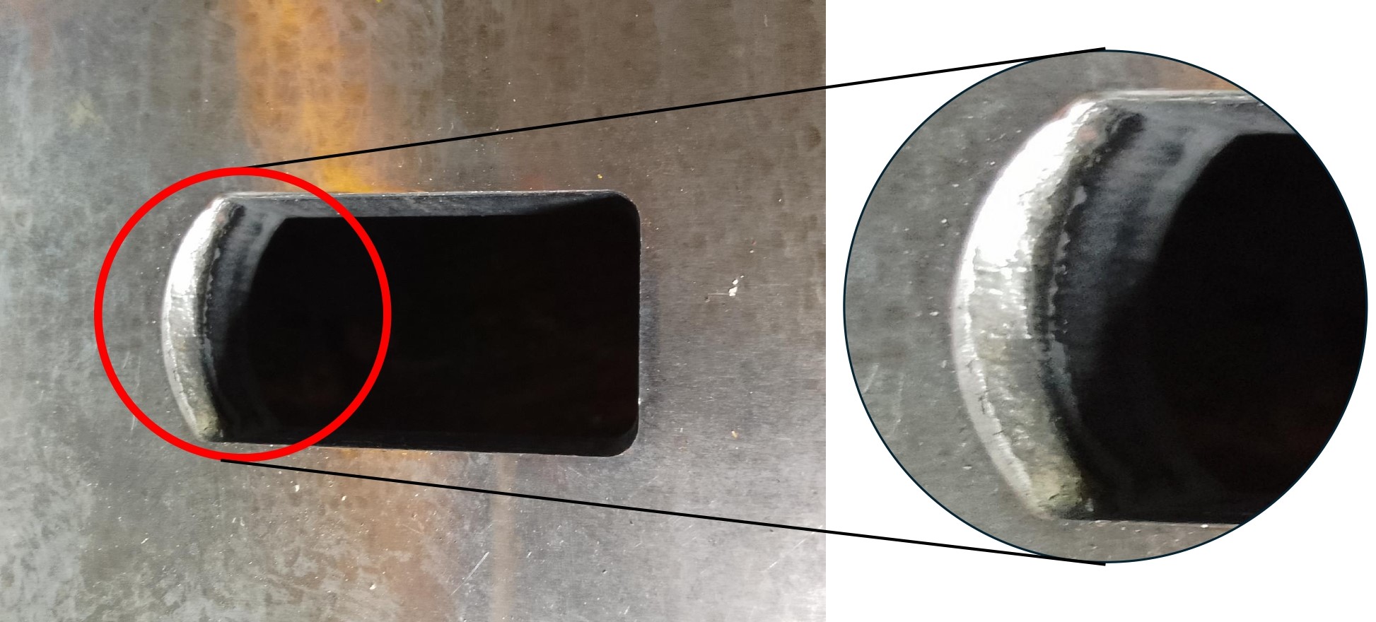
Case 1:
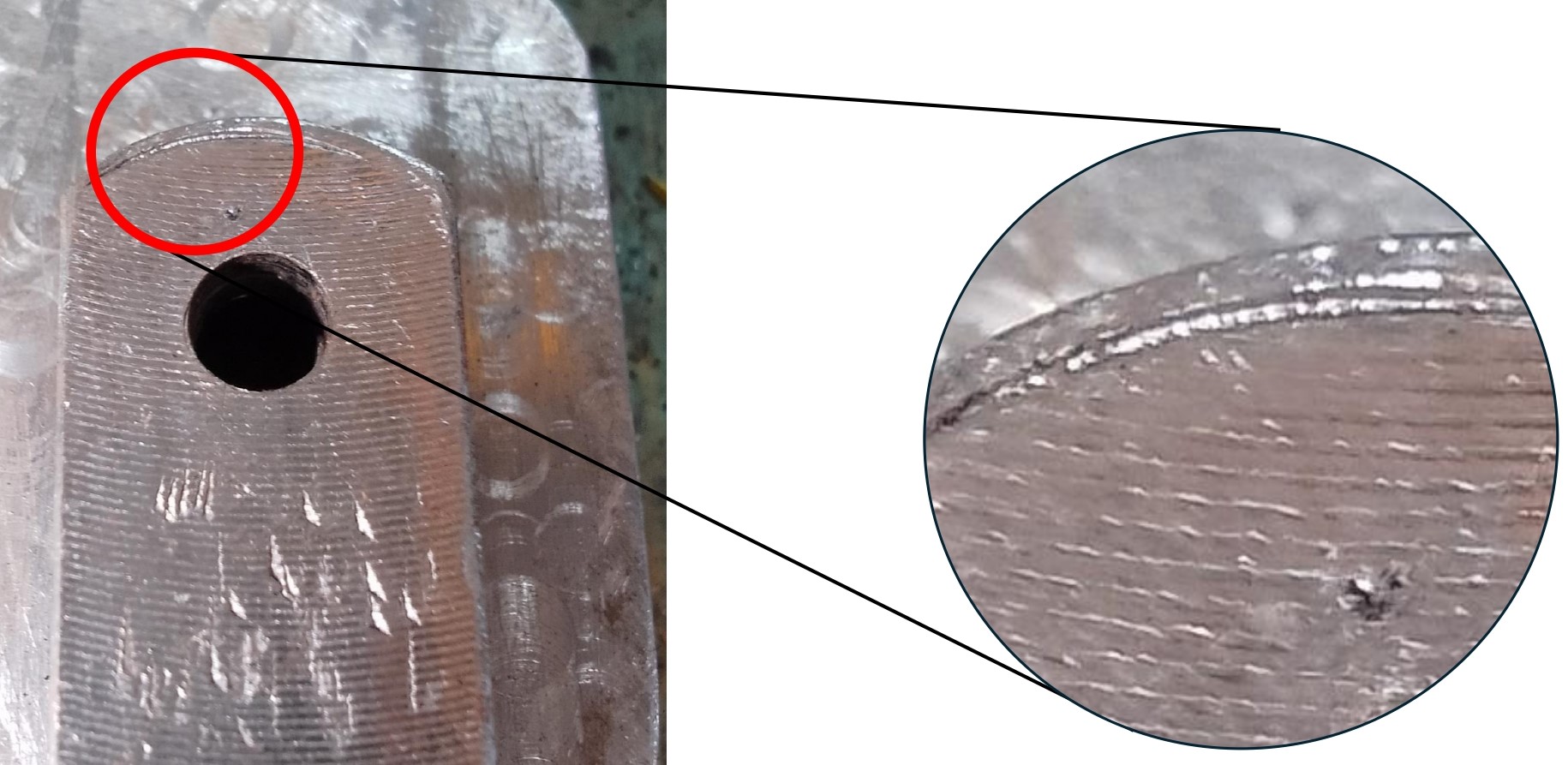
Case 2
In both cases, upper section of the part cannot be blanked successfully due die/puncher severe worn.
Add a commentTooling Evaluation - Case Study 1
During trial, we can know either the tooling working as intended or not. Good design and nice 3D modeling not necessarily free any issued during the fabrication. Precise and good tooling machining and assembly still cannot confirm the tooling will work correctly during the trial. Therefore, progressive improvement thru out the process is crucial. In this article, we will discuss one of the problem that may occur during the trial, i.e. the product not well cut even though puncher-die mark can be seen. There may cause of the raised issue. Below are figures illustrated the said issue.
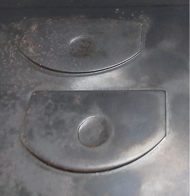
There are many solution, however before that, causes of the defect need to be understood first.
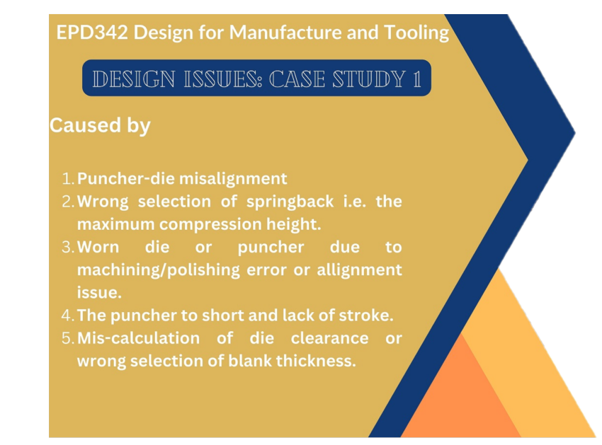
In the next article, the solution will be described together with the proven changes made on the tooling.
Add a commentTooling Design - Material Utilization
Material utilisation is one of the important criteria in tooling design. It can be described as the optimal usage of material in the fabrication of tooling parts. Furthermore, it may shorten the machining time and reduce waste. Figure 1 illustrates an example of material utilization. The material needed for the part in Figure 1(a) is relatively less than the part in Figure 1(b). For about the same function, part (b) has less utilisation compared to part (a).
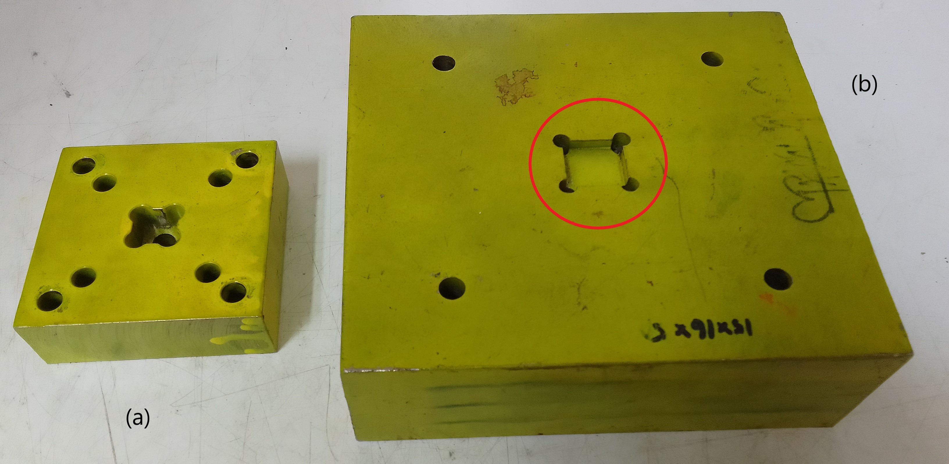
Figure 1: Example of material utilization
One of the reasons to use thicker material is to achieve the adequate height needed for the set amount of stroke by the puncher or die. However, there are many methods to tackle this issue. One of them is by using a simple block, as shown in Figure 2. This approach offers various advantages, including providing space for scrap to drop underneath. The block is relatively simple and requires less time to prepare. The same approach can be applied to the puncher plate.
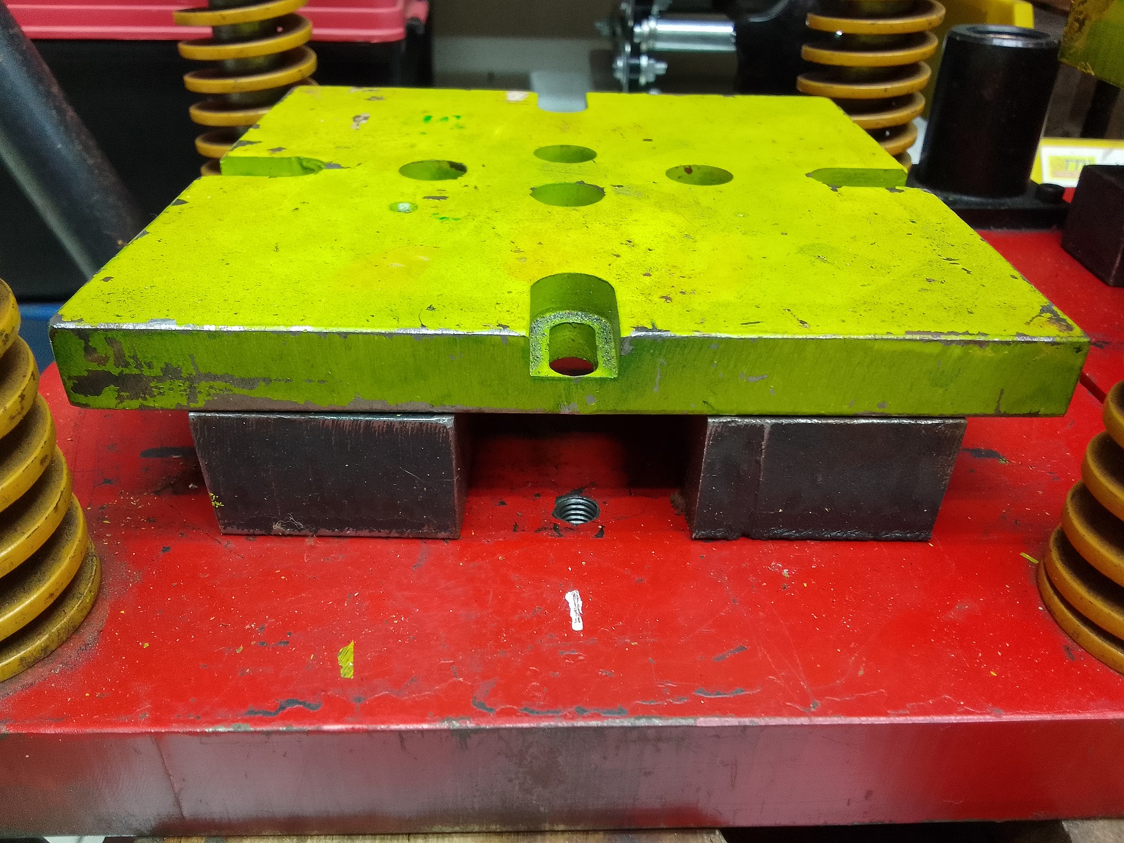
Figure 2: Use of block to raised the die/puncher plate
Note: Images were obtained from the project made by student for their tooling design project.
Add a comment
Congrats Fadzil
Alhamdulillah, Mohd Fadzil Jamaludin, one of our members, just passed his viva voce with a minor correction today. All his sacrifices were paid after the result was announced by the chairman. Congratulations again to him. I hope this can motivate other members of the lab.


The project has huge potential to be implemented in the automotive industry as part of lightweight manufacturing strategies. His project is part of the ongoing research at the Metal Forming Research Laboratory at USM about the initiative.
Add a comment
